Watch a demo
Quick basic engineering design of your step-up substation
PV substation engineering and design in a few clicks


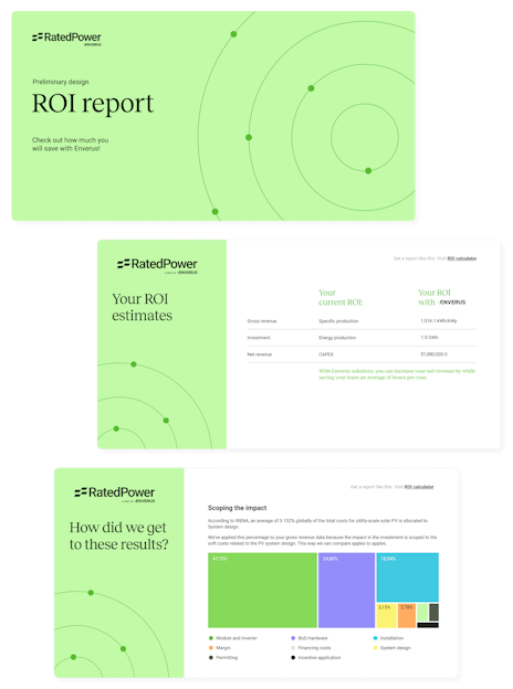
Calculate your ROI from solar, storage and hybrid software
We partnered with Enverus to help utility-scale developers, IPPs, and EPCs uncover just how much ROI they could unlock by implementing solar, storage, and hybrid design software—before their next project even breaks ground.
Automate the basic engineering of your substation and reduce development time
Increase the efficiency, power output, and ROI of your plant’s substation in just a few clicks

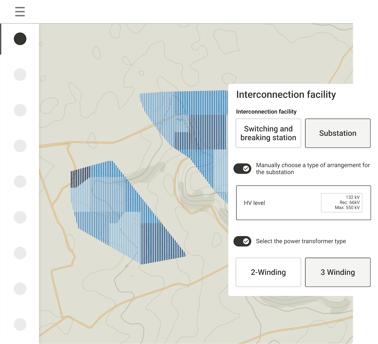
Generate the best interconnection solution

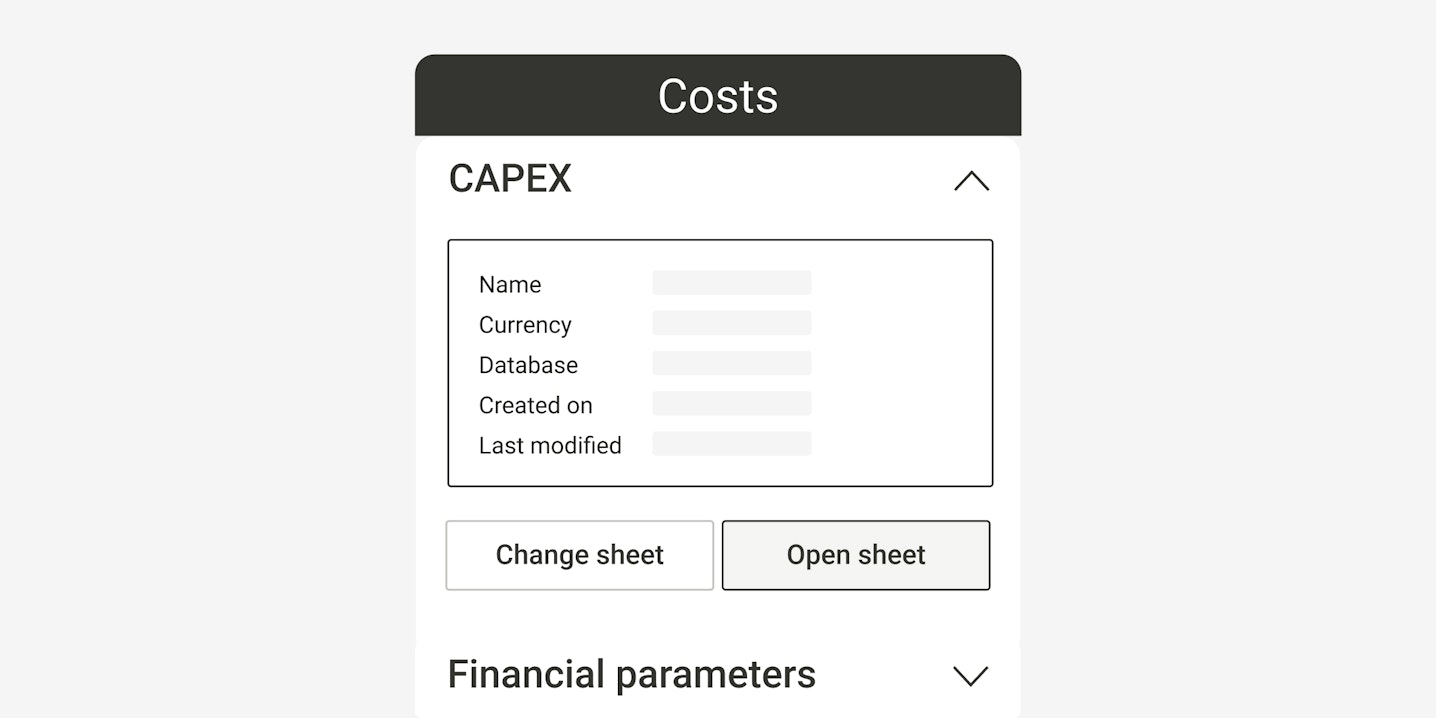
Customize your substation design

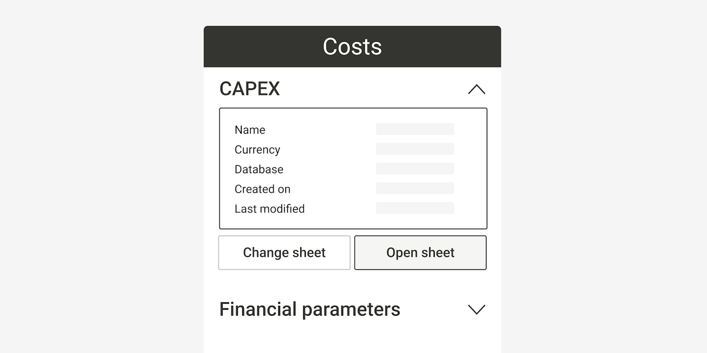
Access cost-effective calculations
Substation design software that grows with you
Basic
Get the basic engineering and feasibility studies for your utility-scale plants all the way to the grid point.
Includes unlimited users, projects and designs.
Advanced
Perform solar PV detailed engineering and get your project ready for off-taker.
Includes unlimited users, projects and designs. Also, everything in Basic plus:
Enterprise
Identify buildable sites, reduce project siting risks, and get the full cycle engineering —from site analysis to detailed engineering.
Includes unlimited users, projects and designs. Also, everything in Advanced plus:
Take a free product tour
Thousands of professionals choose to work with our PV engineering and design software

SolarFarm Feasibility: Building a feasibility business on rapid design iteration with RatedPower
«Using traditional methods, I often found that it would take a lot of time, and a simple change could ripple and really take time and resources away. I built my business on the ability to give people the chance to look at a lot of different versions very quickly and really find the best solution for that site.»


Mulilo: Slashing layout generation time while strengthening stakeholder alignment
«Our turnarounds are a lot quicker now. The turnaround time on everything is maybe 10% of what it was before. Layouts that used to take a couple of hours can now be done in just a few minutes with our templates.»


Res Group: Enhancing project delivery by connecting RatedPower with AutoCAD and PVsyst©
«When manually doing a preliminary site layout in AutoCAD, it can take considerable time and resources. Depending on the size of the site, it can easily take one or two days just for one single scenario. RatedPower’s ability to export layouts as DWG files ensures smooth integration into AutoCAD, helping reduce this workload and speed up design iterations.»


Recurrent Energy: Turning multi-tool workflows into a unified PV+BESS platform
«We have reduced our overall engineering workflow by about 50%, thanks to the platform combining CAPEX estimation, AutoCAD designs, and battery storage simulations. We’ve been able to design several megawatts of storage and it has helped us improve our grid connection applications for stationary BESS projects throughout Europe.»


Akuo Energy: Making smarter use of land with Layout Editor
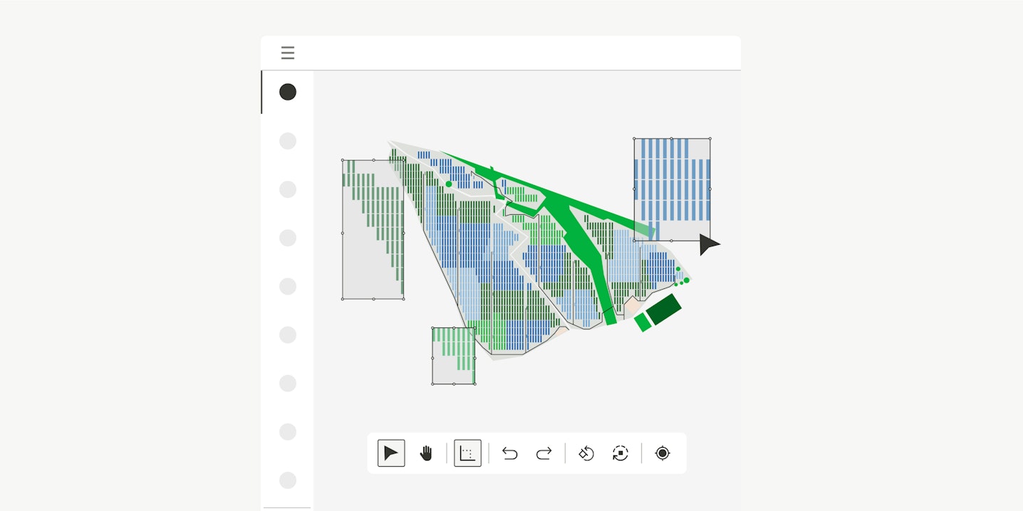
«The new Layout Editor gives us more flexibility to optimize land use, with the option to remove or add structures and align them with parcel borders. It helps us make better use of the total available area of our plant.»


Alten: civil design, BESS & Layout Editor flexibility
«Being able to move trackers and adjust them to fencing or restricted areas directly within the Layout Editor gives us much greater agility when creating designs, because we don’t need to export them to other tools to keep working.»


Photon: Bringing solar design in-house
«RatedPower is truly a value creator. It allows us to develop projects more efficiently while adding significant value to each opportunity. In Japan, tools like this are still not widely adopted, and much of the solar project development process remains manual.»


Ekhi: From feasibility checks to confident designs in record time
«One of the most common challenges we face is space constraints. We need to play around with different tilts and pitch, and this used to be quite a long process with several tools. The great thing about RatedPower is that we can simulate many scenarios, varying all these parameters, and have it done in no time. With the Layout Editor, we now see a huge improvement when fine-tuning our plant layouts.»


Optimizing PV projects and overcoming the limitations of legacy software
«We have received a highly professional response when we needed support or training from the team. RatedPower helps us optimize our projects and provides us with a significant advantage over our competitors.»


Hidrosolar: Unlocking 30% more efficiency in solar design with RatedPower
«We were able to be up to 30% more efficient when making estimates for new projects by having a clearer idea for future developments. So, in terms of time, we could save around 20% to 30%»


Enhancing Hodson Energy’s streamlined project qualification and PV design
«With Enverus PRISM, we quickly filter opportunities and gain a holistic view of viable projects. Enverus RatedPower automates our design process, turning weeks into minutes»


Kickstarting efficient project pipelines
«Although every single engineering aspect and decision is reassessed upon further stages of development, having a pre-made set of rules and standards to start from really helps simplify the development process.»


RatedPower's speed helps us boost our competitive advantage
«Now we can turn around design documents within hours and minutes to stakeholders, landowners, partners or engineers, to get through our regulatory process. This has allowed us to move projects forward faster.»


Accelerating solar design from 5GW to 30GW per year
«Before RatedPower, there was a high level of variability, simple land layout to more irregular layouts. Now, we can quickly filter down sites from what is possible to what is realistic.»


Empowering Recurrent Energy from PV design to financial feasibility
«Of all the solutions we evaluated, RatedPower proved to be the most comprehensive, allowing us to generate layouts, one-line diagrams, reports, energy yield forecasts, and CAPEX & LCOE estimates—all in one platform.»


Empowering solar PV design customization through faster iterations
«In one or two weeks, I became very familiar with the software. I was able to do more iterations on our solar layouts, and we could fill the interconnection requests in no time.»


Enhancing land assessment efficiency for PV developers
«RatedPower produces a set of documentation to deal with most of the environmental agencies' requirements and for application of grid connection authorization processes.»


Competitive positioning in large-scale overseas PV plant bidding
«RatedPower has a solid customer base and good reputation abroad. It delivers required documents in multiple languages for our global bids while adopting international design standards»


Doubling PV project development bandwidth with RatedPower
«Thanks to the new developments created by RatedPower that adapt to our needs, we could double our capacity. The time we used to spend on designing and reviewing designs is now focused on doing more projects.»


Centralizing solar development in one app
«We used to use a mix of tools like AutoCAD, spreadsheets and PVsyst. Now with RatedPower, our team can be innovative and explore more possibilities without wasting time, as each design only takes minutes to run.»


Driving efficiency and optimizing resources for more than 50 projects
«RatedPower offers highly personalized customer support. The team has been efficient in solving our doubts and helping us learn how to make the most out of the tool based on our unique needs.»


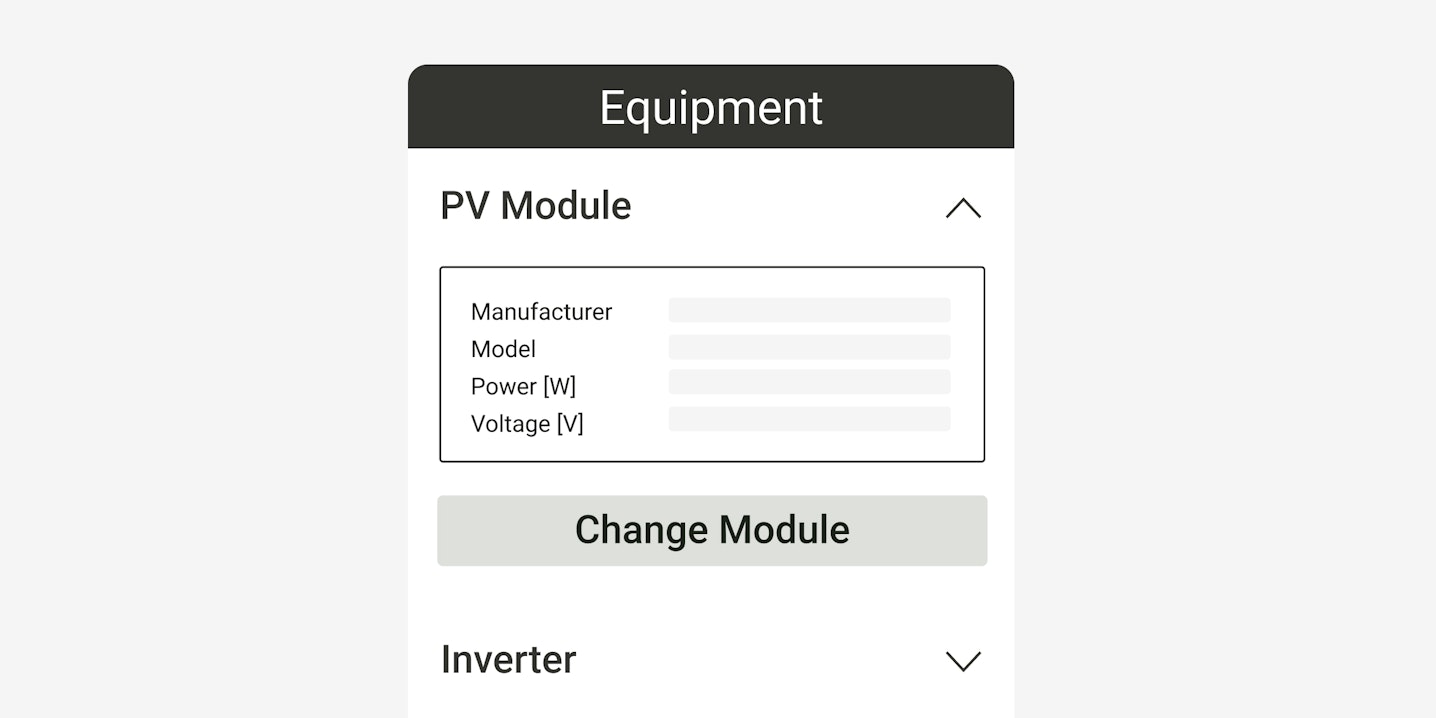
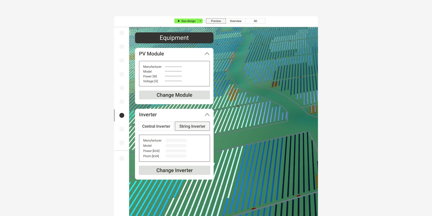
Harnessing RatedPower to carry out invaluable PV equipment analysis
«RatedPower provides us with simplicity and flexibility in our solar projects while requiring fewer resources. Other software options typically demand more resources on our end to complete these calculations.»


A three-in-one software that saves PNE time and resources
«It's easy to use, even for non-technical users. Now, anyone in our offices can efficiently create their own designs, and our German engineers can manipulate anything in our projects remotely since RatedPower's platform is cloud-based.»


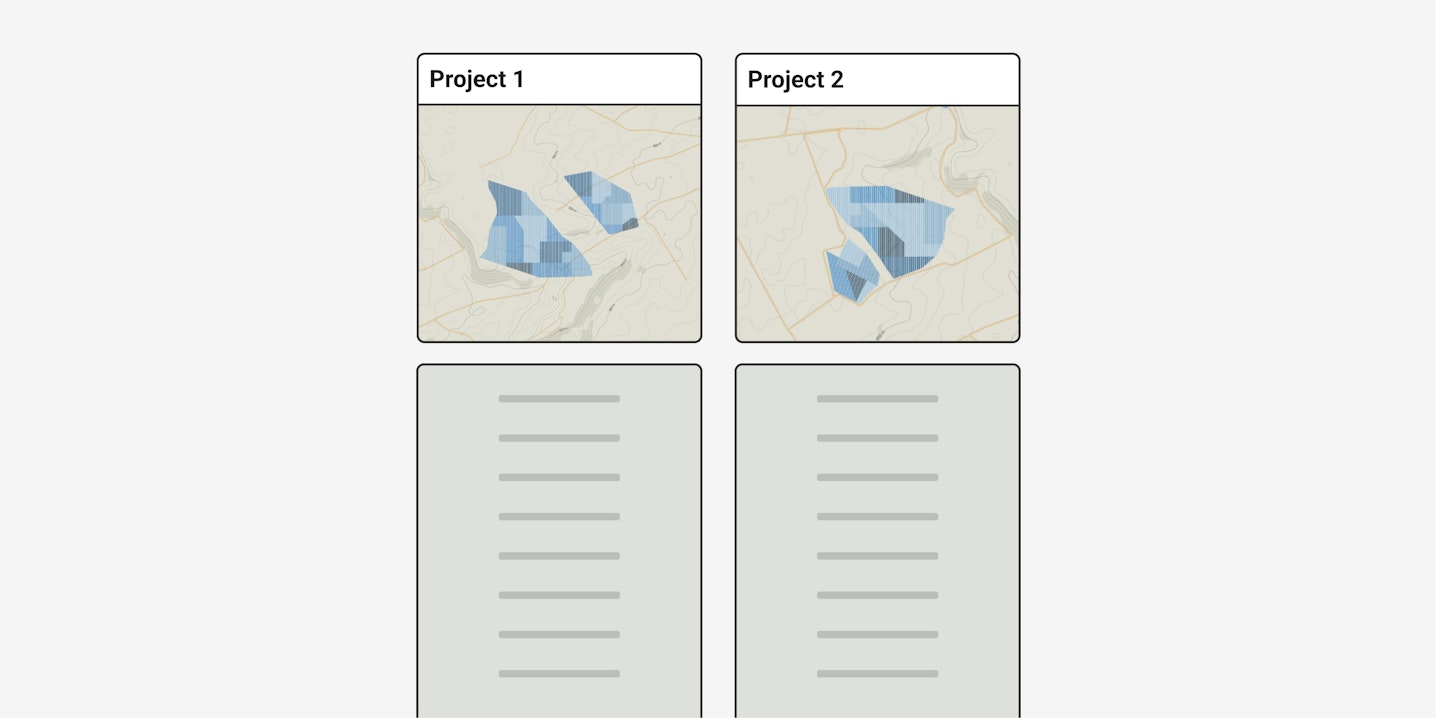
Get real-life inspiration from energy professionals like you
Check how other development and engineering teams are leveraging software to increase ROI and mitigate risks of their utility-scale solar assets.


Learn more
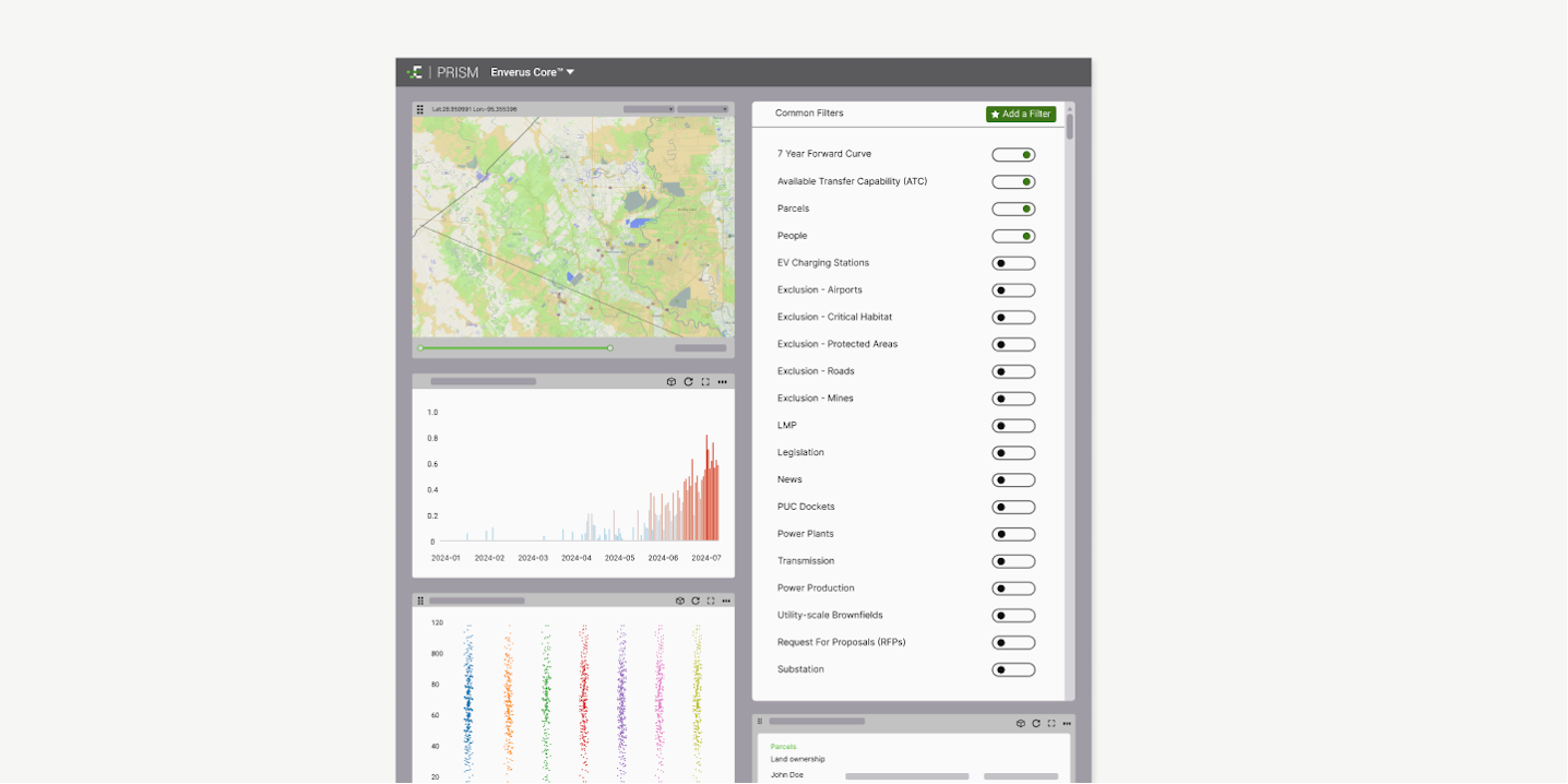
PV site analysis tool
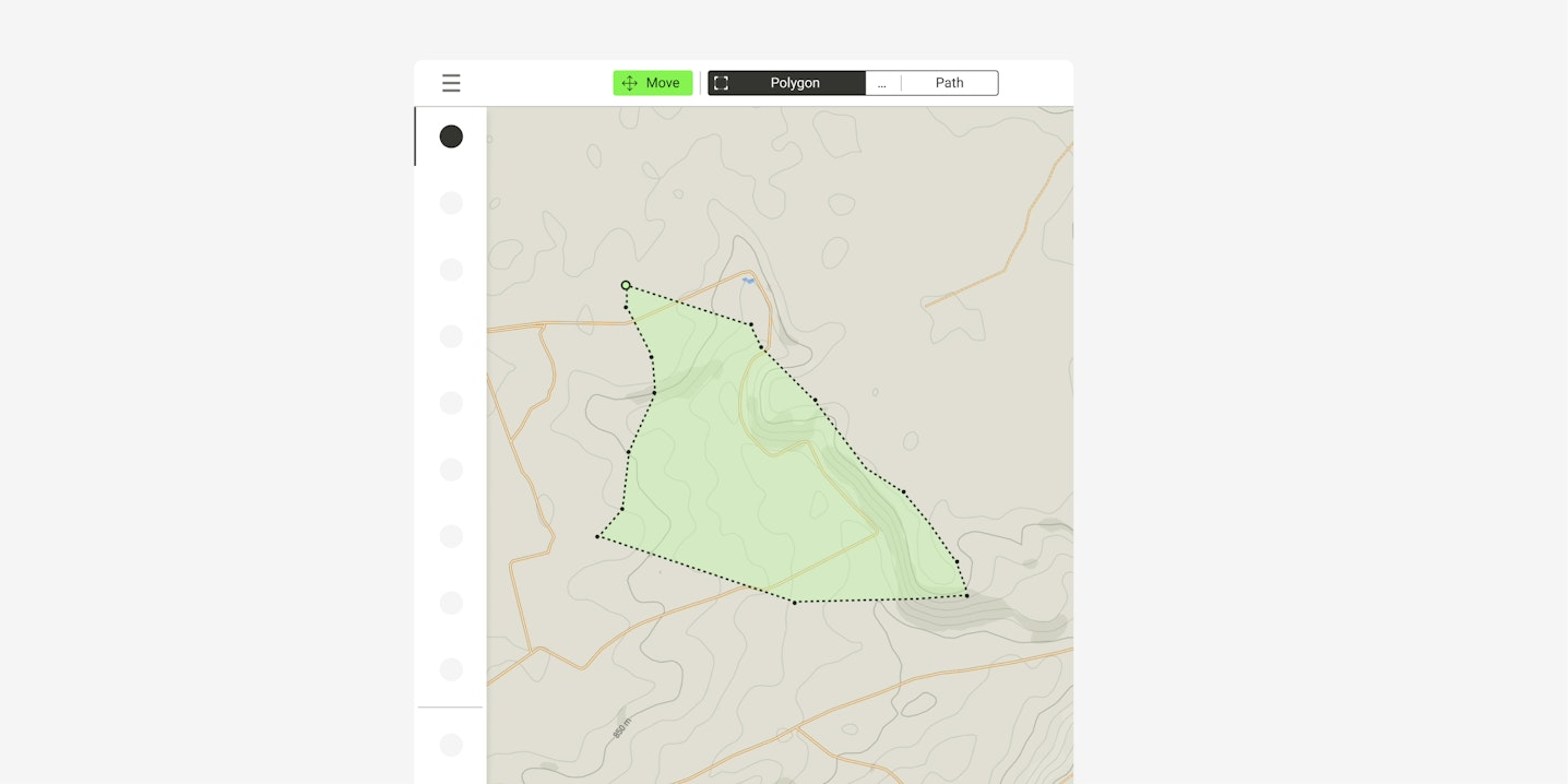
Selecting the right plot of land and mitigating project risks involves considering numerous factors such as interconnection capacity, pricing trends, competition, land suitability, and future economic viability.

Solar planning tool
Equip your development team with smart site assessment, project design, and optimization in a collaborative PV planner.

Solar modeling tool
Reduce risk to your PV project with easy-to-use advanced solar modeling software, increase ROI, and grow your business pipeline.

3D energy yield estimation
Access the most granular energy production estimates with ray-tracing technology and module-by-module analysis validated by real company data.

Battery energy storage system design
The future of utility-scale PV projects is hybrid. Design your BESS and optimize its capacity in one tool. Download basic engineering documents and format its layout in an instant.

Solar proposal software
Slash feasibility assessment times, reduce site analysis costs and boost your PV asset profitability.

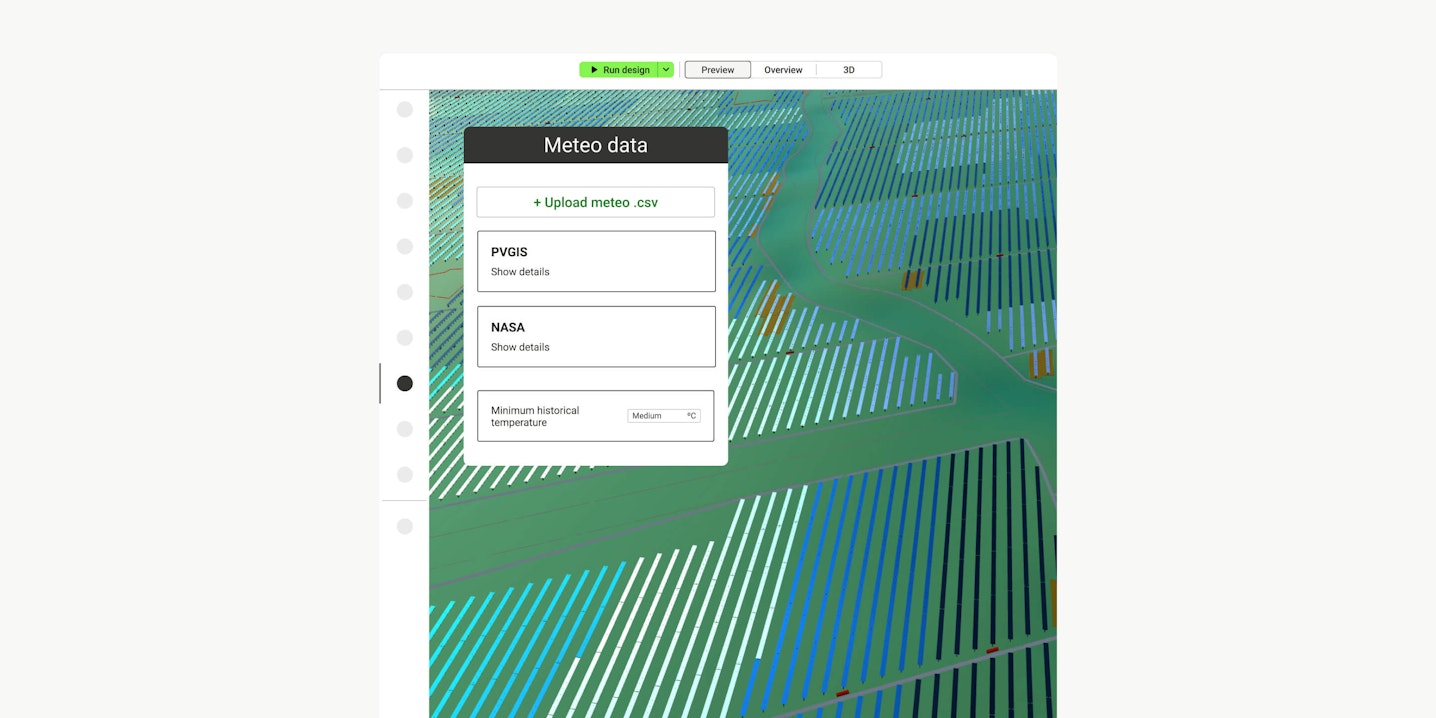
Solar irradiance calculator
Accurate solar irradiance data is the foundation of your future PV plant. You can easily upload your own TMY dataset in .csv or connect to trusted sources to ensure the bankability of your utility-scale solar project.

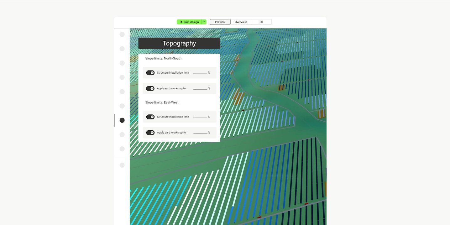
Earthwork estimating software
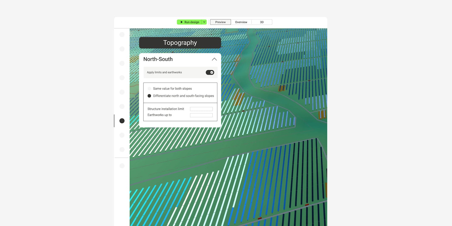
Use the earthwork estimating module to collect more accurate topography estimations for your projects and minimize your financial risk.

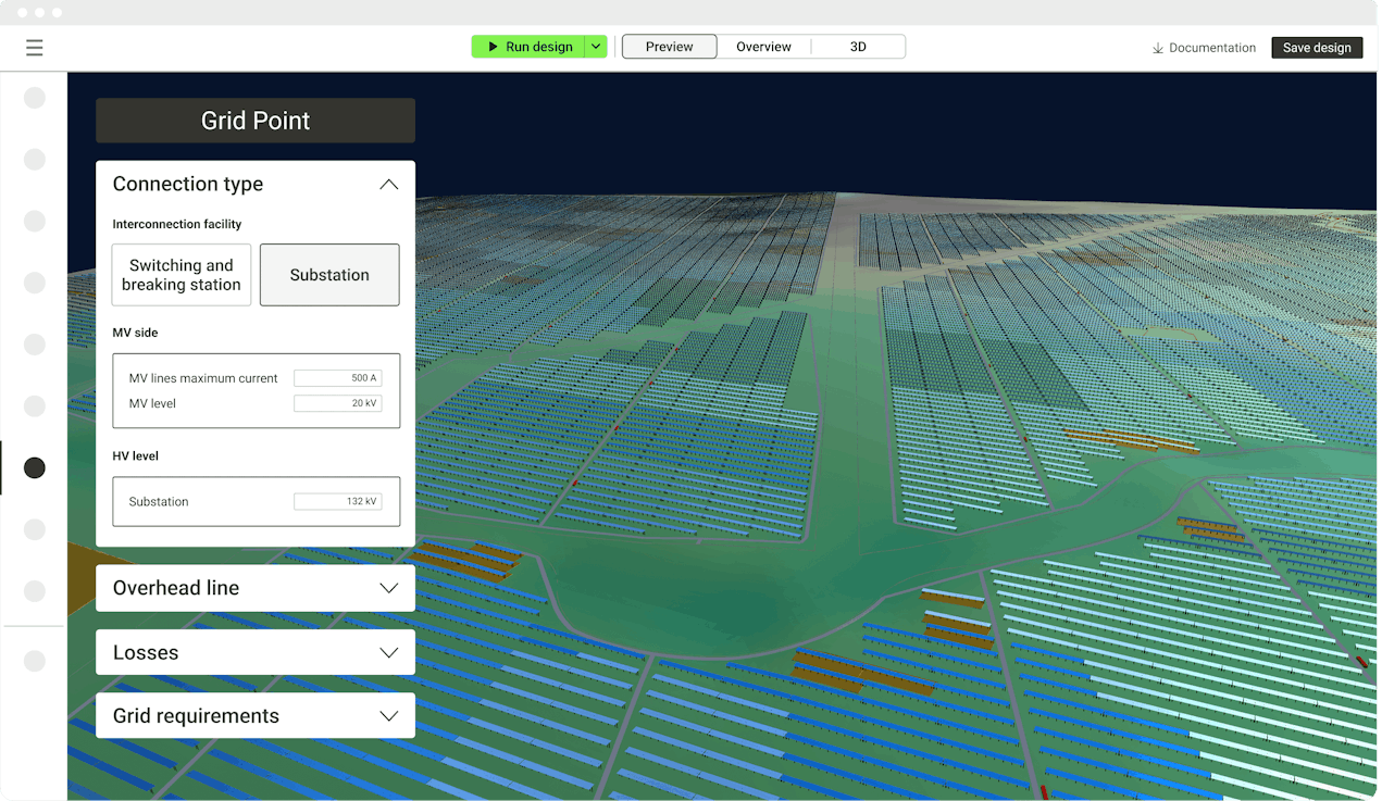
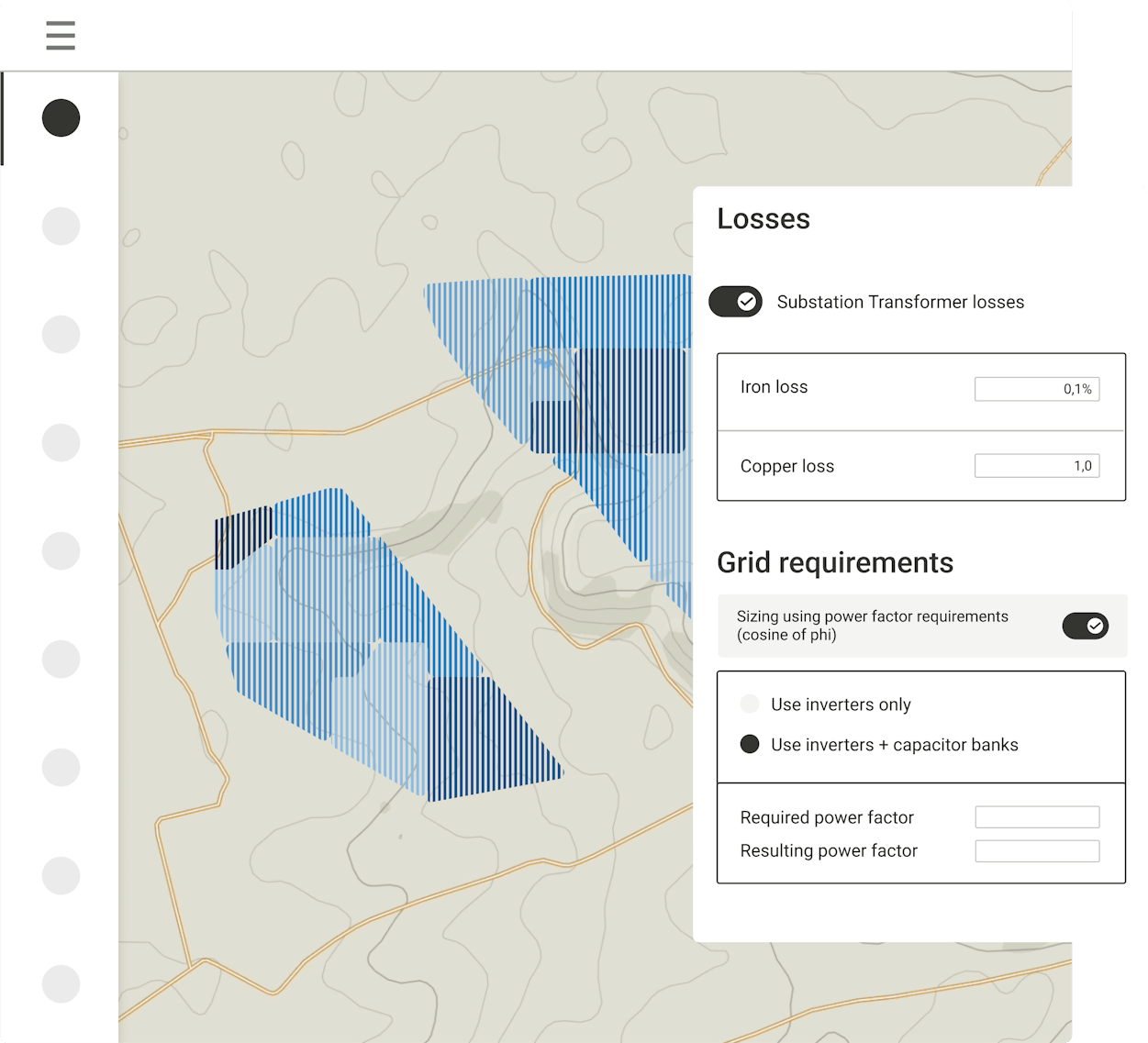
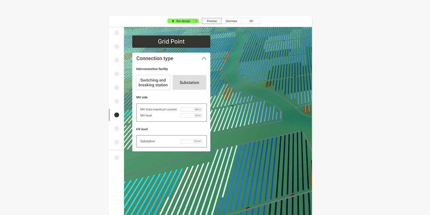
Substation engineering
Easily choose elements such as your facility interconnection type, overhead line type and grid requirements to achieve the highest rated power for your plant while also considering your grid operator, the utility, and the country where it is located

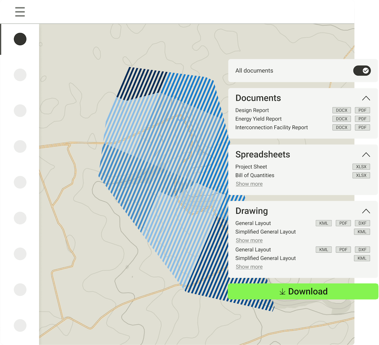
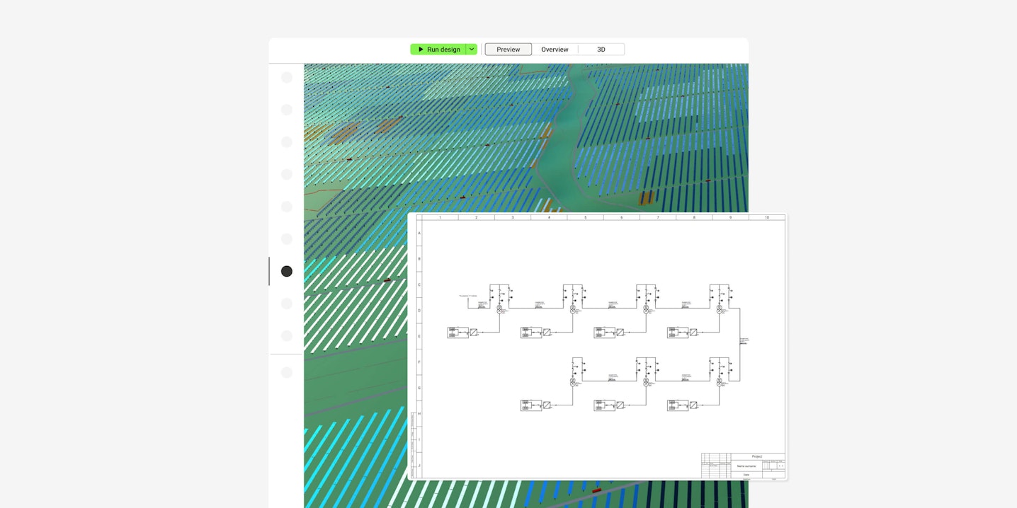
Detailed engineering ready for off-takers
Manually fine tune your automated design with real-time data on energy production—both simplified and 3D, costs and more. Get the project detailed engineering ready for the off-taker.