Watch a demo
Cable standards: Important criteria and differences between countries


Álvaro Pajares
Industrial Engineer
Born in Córdoba and raised in El Puerto de Santa María. Moved to Sevilla to study my Bachelor's and then to Madrid to study my Master´s (Industrial Engineering). During my Bachelor's I spent one year in Padova, Italy (where I learnt about Photovoltaics and how to cook the real pasta carbonara and risotto) and during my Master's I spent one year in Tampere, Finland (where I learnt how to live without sunlight). After coming back from Finland, I joined RatedPower!


Content
Calculating the output of your plant with the correct cable standard will be imperative for a correct sizing and configuration of the electrical side of your plant.
Although cable sizing may appear less imperative in the design process of your solar plant, as other traditional desktop software don’t even carry out this analysis, in RatedPower we know that cables may have a huge impact on the costs and the efficiency of the system.
How to choose your cable standard
Choosing the correct cable size for your region and knowing their restrictions and requirements will be essential when designing your site and adjusting to the best possible LCOE of the plant. In the end, according to IRENA [PDF], cabling, wiring and electrical installation costs are on average 10% of the total costs of a solar plant (approximately 2,200 USD/kW), so planning ahead to reach their maximum capacity and configuration could potentially reduce the total cost.
In reality, cable standards may be more or less restrictive depending on the operating conditions of the grid, so let’s take a closer look at their differences and analyse how RatedPower performs.

For the calculation of the minimum cross-section required when sizing a cable, three criteria are usually used to ensure its correct operation:
Current-carrying capacity: maximum admissible current under the cable's operating conditions.
Voltage drop: maximum admissible voltage drop. Failure to comply with this criterion will not prevent the correct operation of the cable, but it will mean an increase in the losses of the installation.
Short-circuit temperature rise: will limit the energy loss that may occur during the short-circuit and therefore the maximum temperature the cable can reach.
For the fulfillment of each criteria, a minimum section will be required and the most restrictive will determine the section that will dimension the cable. For the calculation of the section that satisfies each criteria, there are standards that establish the steps to be followed and the operating limits of the cables for each one of them. These standards will be based on the typical operating conditions of the geographical area to which they refer, and may be more or less restrictive when sizing cables.
Do you want to learn how to optimize the number of modules per string in your utility-scale PV system? Check out this recording of our free webinar!
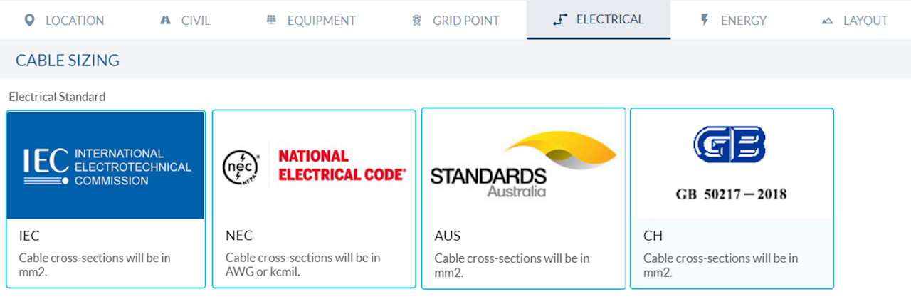
The following are the guidelines that the different standards usually follow to meet these criteria and the most notable differences that may exist for each of them. In this article we have made use of the RatedPower functionality that allows sizing the cables of a PV plant according to four different standards: IEC, NEC, Australian Standards and Chinese Standards.

Current-carrying capacity
In order to know the maximum admissible current for a cable with a given cross-section, the following parameters must be known:
Cable structure: conductor material, insulation and number of conductors per phase.
Cable installation: cable installation method (tray, buried or other), distance between circuits and depth of buried cable (if applicable).
Cable operating conditions: ambient temperature, soil temperature and resistivity (if applicable) and other operating conditions that may affect sizing (such as distance to other elements of the installation or application of use).
When calculating the maximum admissible current for a given cable cross-section, the different standards generally use the same structure:
The maximum admissible reference current is obtained from the cable structure, type of cable installation and reference conditions in accordance with the country of application of the standards (both environmentally and for the installation).
Once the maximum admissible reference current is known, it is necessary to obtain the correction factors that adjust the maximum admissible current to the real operating conditions. These factors will take into account both the type of installation and the cable operating conditions.
This criteria will impose a limit mainly in shorter cables, as could be the case of string or low voltage cables in photovoltaic installations.
In order to evaluate the different standards and to know the differences that each of them may present, we have proceeded to evaluate what would be the minimum section required for an installation of 6 single-pole low voltage DC aluminum cables with XLPE insulation (or XHHN for NEC standards) with an operating current of 100 A buried at a depth of 0.2m without separation and with a soil temperature of 10ºC and a soil resistivity of 2.0 K-m/W. The results obtained are shown in the following table:
From these results it can be seen the importance of taking into account the real operating conditions of the cable and how each standard can be more or less restrictive. For the standards evaluated, it can be seen that the Chinese standard is going to be the least restrictive, where a smaller section could be used for cable sizing.

Voltage drop
In order to know the voltage drop that can occur along a cable route, the following parameters are necessary:
Cable structure: cross section, conductor material and insulation. These last two will determine the resistance and reactance of the cable.
Cable length: the longer the cable, the greater the voltage drop. Therefore, this standard will be a limiting criteria for longer cables, as may be the case for medium voltage cables in a photovoltaic plant.
Cable operating conditions: operating voltage and current.
For the calculation of this value, the different standards are usually in alignment, providing a resistance and reactance value according to the conductor material and insulation of the cable which, together with the length of the cable and the operating current and voltage, will determine the minimum cross-section necessary for the voltage drop to be lower than the required value. As previously mentioned, failure to comply with this criterion would not prevent the correct operation of the cable, but it would mean an increase in the losses of the installation.

Short-circuit temperature rise
As for the voltage drop calculation, to calculate the minimum cross-section necessary to ensure that the cable temperature does not exceed the cable temperature limit under short-circuit conditions, it is necessary to know the cable structure. In addition, the cable and short-circuit operating conditions will be used to know this value.
From the cable structure, a constant will be obtained which, together with the short-circuit current and the short-circuit duration time, will define the minimum cross-section necessary so that the maximum temperature allowed by the insulation is not exceeded.
Again, the different standards are generally aligned when calculating this requirement and follow the same procedure.
All in all, for cable sizing, the guidelines to be followed will generally be stipulated by the regulations in force in the geographical area in question. These regulations will generally be based on typical operating conditions in the country and may be more or less restrictive. However, all of them will follow the structure explained in this article and will require compliance with the criteria of maximum ampacity, maximum voltage drop and short-circuit current.
We hope you found this article interesting, if you are interested in seeing how simulating with one standard or another may impact both the energy output and the LCOE of the plant, be sure to reach out to us for a free platform guided tour.
Latest stories
Related posts
Technology and engineering
How 3D Planning Is Accelerating Solar Deployment in Finland
Find out how 3D solar design and digital permitting are transforming Finland’s energy development, streamlining workflows, and ensuring regulatory compliance.
Updated 24 MAR, 26


Technology and engineering
Outsmarting congestion: How efficient solar design helps navigate Nordic grid limits
Learn how Nordic operators and solar developers are adjusting to tighter grid conditions and how policy and design decisions are keeping projects on track.
Updated 16 DEC, 25

Technology and engineering
The rise of ultra-thin perovskite solar cells
Learn about Japan’s $1.5B initiative to commercialize ultra-thin, flexible perovskite solar cells and how it could transform the solar landscape globally.
Updated 30 SEP, 25