- Solar energy blog
- How to design an optimal solar PV system
How to design an optimal solar PV system
Roll up your sleeves and learn how to design an optimal solar PV system. Get a perfect project layout easily with RatedPower.


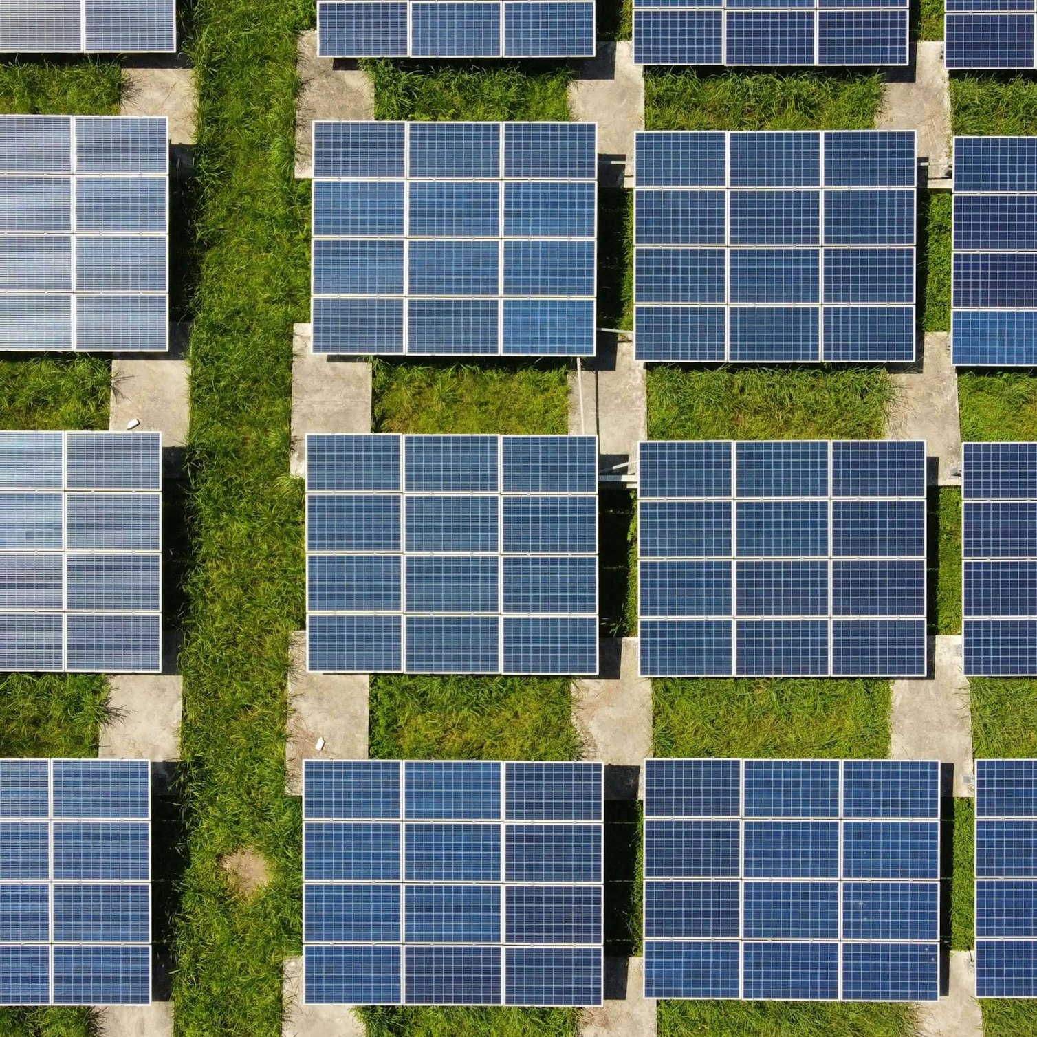
RatedPower is a platform that allows you to optimize your solar PV designs quickly and efficiently. In the last few months, we have implemented some game-changing improvements, which have significantly reduced the simulation time and improved the structure grouping algorithm. These new parameters will help you ensure your site is filled with structures with the most optimal design configuration.
At RatedPower, our aim has always been to simplify the work of solar PV engineers by automating all the tasks they perform on a daily basis. From the start, our goal was for RatedPower's algorithm to focus on specific aspects of the design of a PV plant.
These include the automatic positioning of structures, roads, power stations, cables, and more. Other important aspects are the calculation of cable cross-sections in accordance with different electrical standards, the energy production calculation, the substation engineering, and the generation of all the necessary documents and drawings related to each design.
This algorithm has always been evolving. We hope to shed light on some of the latest developments that the layout algorithm has experienced and guidance on how to optimize your design.
In this article, you will learn how to define some parameters that will help you optimize your PV plant, such as choosing the type of layout, determining the DC/AC ratio, or sizing your equipment.
So, buckle up and enjoy the ride!
How can a solar developer optimize their PV plant projects at the very early stages? Watch our recorded webinar session, Early-stage PV project optimization: a developer POV, to find out!
Layout Parameters and Optimization
You have at your disposal numerous layout parameters that you can adjust in real time to see how they affect the final layout result. Here’s how to use these layout parameters to get the most out of them:
Type of Layout
First, you can select the type of layout you want among the following options:
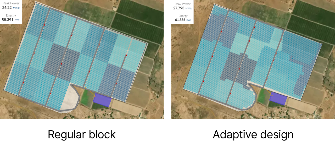
Regular blocks: This option defines a rectangular block of structures belonging to one power station and repeats it throughout the layout. This configuration is better for large PV plants with regular area definitions.
Adaptive design: With this option, each power station (PS) can have different sizes (power) and different DC/AC ratios, so the design complies with the global parameters set by the user. This allows for power stations with different shapes that better fit the perimeter and irregularities of the site, resulting in more total installed capacity.
DC/AC Ratio
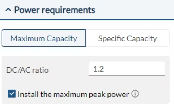
The layout design tab allows you to define the DC/AC ratio. This ratio primarily depends on the PV module, the inverter, and the structure you have chosen. Other parameters, such as the number of modules per string, strings per structure, and structures per inverter, will also influence this ratio.
You can also enable the "Install the maximum peak power" checkbox. By activating this option, all possible structures will be installed in the PV plant, reaching the maximum possible peak power by varying the DC/AC ratio within a maximum of +/-0.15.
Using Secondary Inverters
Another option to consider when trying to fill in those remaining portions where the chosen inverter cannot fit in, is to utilize a smaller, secondary inverter. When no more power stations can be placed on the site (size-wise), this option will allow you to try to place smaller power stations using the secondary inverter.
Setbacks
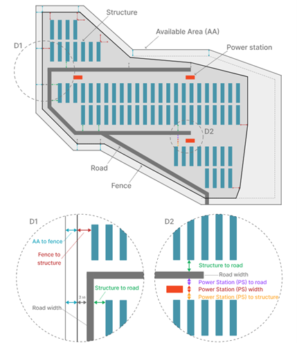
To further personalize and optimize your layout design, RatedPower offers several setback options that you can define between different elements within the PV plant. By selecting and adjusting these setbacks, you can fine-tune the layout to achieve the best possible configuration.
Standard Setbacks
Available Area (AA) to fence
Fence to structure
Power Station (PS) to structure
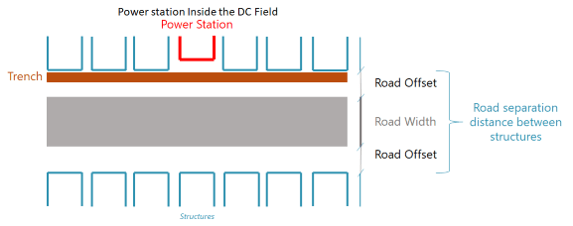
Power Station (PS) to road
Structure to road
New Setbacks for Restricted Areas (RA)
Restricted Area (RA) to fence
Restricted Area (RA) to structure
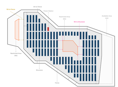
In addition to these, we have introduced new fence strategies that interact with Restricted Areas (RA), providing more options for optimal layout configuration:
Prevent the Fence from Crossing RA
Keep RA Inside the PV Plant
Let the Fence Cross RA
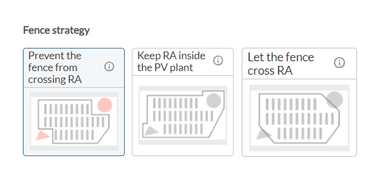
By carefully selecting the most appropriate fence strategy and setbacks for your Restricted Areas, you can further optimize the overall design of your PV plant, ensuring maximum efficiency and utilization of space.
Structure position
Optimize your layout by adjusting the orientation or offset of your structures relative to the parcel’s borders. You can choose from the following four options:
Standard: Structures follow their usual axis direction.
Rotated: Structures are rotated in blocks.
Offset: The axis of the block is rotated while keeping the structures aligned.
Turning Angle Axis: Structures are rotated while keeping the block aligned.
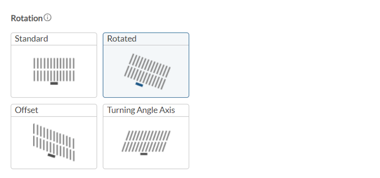
For linked-row trackers, the last two options are not available.
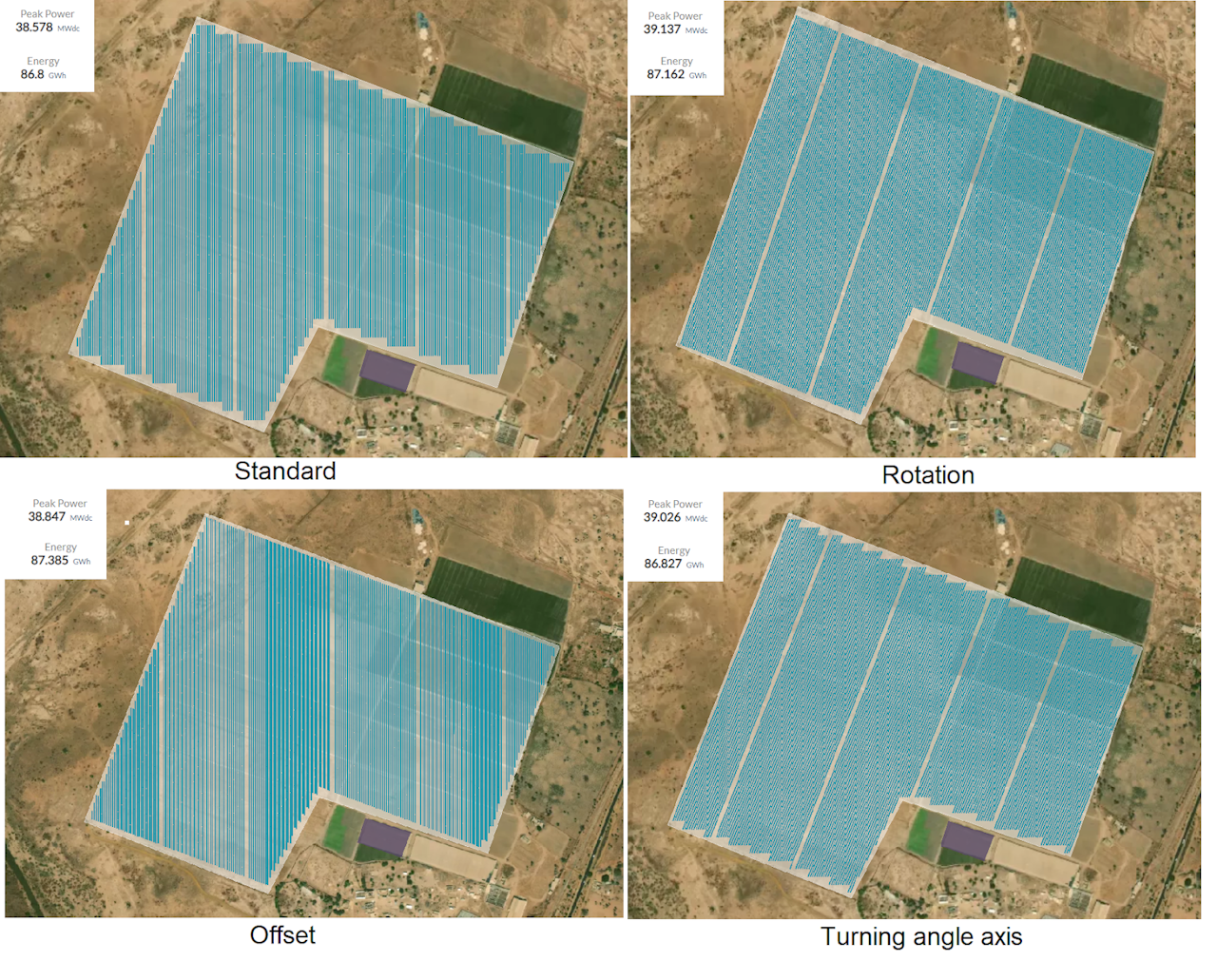
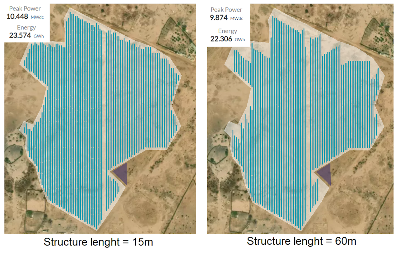
Using smaller structures or enabling Partial Structure
When your site is too small or contains a lot of irregularities, you can maximize the layout by using smaller structures. This is achieved by reducing the number of modules per row, which can be adjusted using two parameters in RatedPower: the number of modules per string and the number of strings per structure. For tracker systems, you can also opt for smaller structures with fewer modules per row.
In addition, there is also the option to enable partial structures. This feature can be activated from the Equipment tab under Structure.
By enabling partial structures, if you have a configuration with more than one string per structure, the software will allow the placement of structures with fewer strings, even down to one string per structure.
This enables the filling of any remaining spaces that cannot accommodate the original configuration, optimizing the overall layout of your PV plant by ensuring that no usable space is left empty.
Power stations
RatedPower allows you to optimize the placement of power stations within your PV plant.
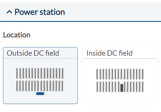
Placing the power station inside the DC field will remove one structure from the block connected to it, but will result in shorter distances between structures, generally leading to more total installed capacity.
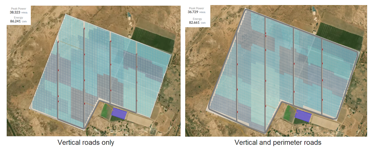
Roads
There are seven road configuration options in RatedPower:
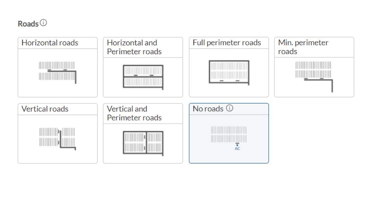
Based on the needs of your PV plant, you can select one of the above options. The two possibilities without perimeter roads install PV modules all the way till the border of your parcel thus allowing you to install more total capacity.
Only Horizontal Roads: Connects all Power Stations in an East-West direction to the access points.
Horizontal and Perimeter Roads: Combines East-West routes with perimeter roads.
Only Vertical Roads: Connects all Power Stations in a North-South direction to the access points.
Vertical and Perimeter Roads: Combines North-South routes with perimeter roads.
Full perimeter roads: Installs roads around the perimeter of the available area, ensuring all Power Stations are connected and accessible from every direction. This option is only available if there are no more than 5 Power Stations within the available area.
Min. perimeter Roads: Focuses on minimizing the length of the perimeter roads, ensuring connectivity with the least amount of road coverage around the available area. This option is only available if your available area contains no more than 5 Power Stations.
No Roads: No internal roads are created within the available area, optimizing the space for maximum structure placement. This is only an option if the available area contains just one Power Station, which will be placed as close as possible to the AC point within the area.
Structure alignment
Here, you can choose between two options:
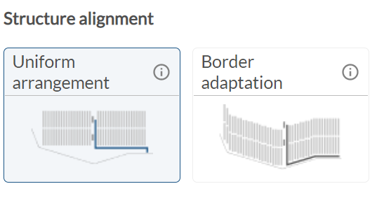
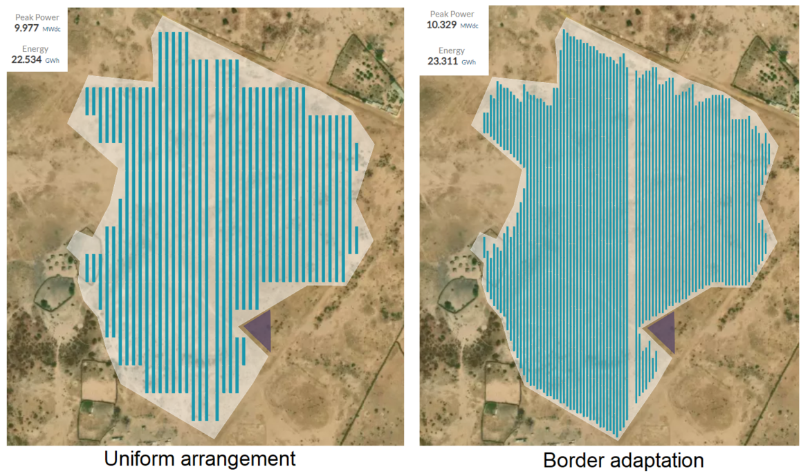
This parameter lets you choose between linear uniform positioning or adapting structures to the parcel’s border. Border adaptation can increase total capacity but may complicate construction. The choice between horizontal or vertical roads will also influence this alignment, with border adaptation taking effect based on the direction of the roads relative to the structures' axes.�
Final adjustments to your design
As discussed above, several relevant design configurations have been developed which enable you to tweak your design to perfection! Another parameter to consider is the pitch distance, which influences not only the ground coverage ratio but also the shading losses. For even more tips, check out our blog about the tilt angle for fixed structures for higher system efficiency.
Latest stories
Related posts
Technology and engineering
Outsmarting congestion: How efficient solar design helps navigate Nordic grid limits
Learn how Nordic operators and solar developers are adjusting to tighter grid conditions and how policy and design decisions are keeping projects on track.
Updated 16 DEC, 25
Technology and engineering
The rise of ultra-thin perovskite solar cells
Learn about Japan’s $1.5B initiative to commercialize ultra-thin, flexible perovskite solar cells and how it could transform the solar landscape globally.
Updated 30 SEP, 25

Technology and engineering
The green hydrogen boom in LatAm
Latin America is emerging as a green hydrogen leader. Learn how LatAm countries are leveraging solar and wind power to drive green hydrogen production.
Updated 22 JUL, 25
- RatedPower
- Solar energy blog
- How to design an optimal solar PV system
 Watch a demo

