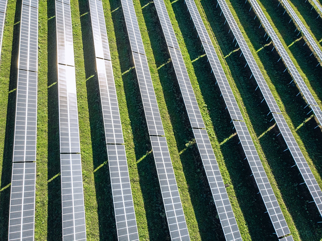
What is a phase conductor and how is it used in solar plants?


Jeremy Vickerman
Senior Content Manager
Senior Content Marketing Manager at RatedPower with extensive experience in content strategy, production, and communications. Over a decade of expertise spanning marketing, recruitment consulting, and public relations across the UK and Spain, with a strong track record in driving brand visibility and audience engagement.


Enio Gjoni
Sr. Product Owner
Enio Gjoni is an electrical engineer with expertise in power system analysis and studies. Having dedicated 5 years contributing in the "Control Room of the Future" for transmission utilities, by being part of the implementation team of cutting-edge SCADA/EMS/AGC systems, he has joined RatedPower as a Senior Product Owner in the Interconnection team, committed in bringing to the users a top-tier software solution for solar power studies.
What is a Phase Conductor?
Phase Conductor definition: A phase conductor is a live conductor under normal conditions that transmits electrical energy. They are used alongside neutral conductors to provide power for AC electrical equipment.
Phase Conductors are often referred to as “live parts” as they are energized under normal conditions. They are current-carrying conductors and are counted in the total number of electrical conductors that are used in an electrical circuit, network or system.
Single-phase vs. three-phase power
With electricity, “phase” refers to the load distribution. When working with electricity, you will come across two key phrases: single-phase and three-phase power. The difference between single-phase and three-phase power comes down to the wiring. Single-phase power supplies have one phase wire and one neutral wire, with current running between the two. Three-phase power requires three phase wires and one neutral wire, with each phase AC signal 120 electrical degrees apart.
One key distinction between single-phase and three-phase power is the load capacity. A three-phase system can handle higher concurrent loads compared to a single-phase supply. So single-phase power supplies are usually found in residential buildings with a typical voltage of 230 V. The voltage of three-phase power supplies is higher, generally around 400 V, which is why they are primarily installed in commercial and industrial buildings that use a higher load.
Single-phase systems can be created from three-phase systems to achieve the correct voltage. This is done via a transformer in the US or performed directly within the EU.
Another notable difference between single-phase and three-phase systems is the consistency in delivering power. A single-phase system offers significantly more peaks and dips in voltage, whereas a three-phase system offers power at a steady, constant rate.
Three-phase electrical systems do not require excessive conducting materials to transmit electrical power, making it a more cost-effective option for electric transmission on a larger scale. However, the three-phase connection is not able to handle overload. Any overload to the system may damage equipment, offsetting the cost savings by needing to replace and repair components.
Phase conductors and solar plants
Solar PV generates electricity as DC, which needs to be converted to AC before it can be used by electrical circuits and domestic appliances. To do this, DC electricity needs to be sent to a solar inverter. A solar inverter channels DC electricity through a transformer, which changes the electricity to AC.
Once you have converted your solar energy into a usable power supply, you need to identify whether you require single-phase or three-phase power. What you are using the power for will determine the number of phase conductors and the types and sizes of cables required in your system.
There are also different inverter types for each system type. A single-phase connection is simple, requiring a single-phase solar inverter. When it comes to a three-phase connection, you have a couple of options. The simplest option is to install a three-phase inverter which will distribute power evenly across each phase.
With three-phase connections, you can also choose to install one single-phase inverter on one of the phases, typically the phase with the heaviest loads. However, this can cause potential issues. If you expand your system beyond the inverter’s capabilities, you risk tripping the inverter as the voltage increases.
Choosing the suitable cable for your solar PV plant is important. Cable size can affect the performance of your entire system. Each cable size can only accept a certain amount of amperage and voltage, so the thicker your cabling, the more power your solar PV system can handle. Say you install a smaller cable than recommended; you risk voltage drops, energy surges, and potentially electrical fires. It’s also worth noting that DC and AC electricity require different cable types.
Request a demo today to see how Rated Power can benefit your PV plant design.
Design utility-scale solar at lightning speed
Plotting Your Overhead Lines with pvDesign
Download the guide to take a deeper look at overhead lines and learn how to incorporate them into a utility-scale project using pvDesign.
Latest stories
Related glossary posts
Technology and engineering
How solar zenith and azimuth impact panel efficiency
Updated 8 SEP, 25
Technology and engineering
Albedo and Solar Power: What You Should Know
Updated 8 SEP, 25
Technology and engineering
What is a solar substation and how to customize yours with RatedPower software
Updated 5 MAY, 25
Related posts
Technology and engineering
Outsmarting congestion: How efficient solar design helps navigate Nordic grid limits
Learn how Nordic operators and solar developers are adjusting to tighter grid conditions and how policy and design decisions are keeping projects on track.
Updated 16 DEC, 25
Technology and engineering
The rise of ultra-thin perovskite solar cells
Learn about Japan’s $1.5B initiative to commercialize ultra-thin, flexible perovskite solar cells and how it could transform the solar landscape globally.
Updated 30 SEP, 25

Technology and engineering
The green hydrogen boom in LatAm
Latin America is emerging as a green hydrogen leader. Learn how LatAm countries are leveraging solar and wind power to drive green hydrogen production.
Updated 22 JUL, 25
- RatedPower
- Glossary
- P
- Phase conductor
 Watch a demo