- Solar energy blog
- Cable sizing: Soil resistivity and temperature
Cable sizing: Soil resistivity and temperature
How do soil conditions affect the cable requirements in a solar photovoltaic plant? Here, we’ll dive into how RatedPower can help you account for the impact.


Content
The performance of electrical cables in a solar photovoltaic (PV) system is affected by numerous soil factors, including but not limited to, the surrounding temperature and spacing.
When project designers fail to take these variables into account, they increase the risk that the installed cables will be the wrong size. Cables that are too large incur unnecessary costs, whereas if the cables are not large enough, they may not comply with international standards. At worst, incorrectly sized and installed cables can cause personal injury or damage to the system equipment.
What do you need to take into account about the soil conditions when designing the cabling in a PV system? And how can you optimize your cable size?
Join us for our most awaited webinar on topography restrictions in PV plant modeling, where we'll dive into the essential factors to consider when designing and modeling a PV system, including the impact of topography on the system's design and output.

How does soil resistivity affect cables?
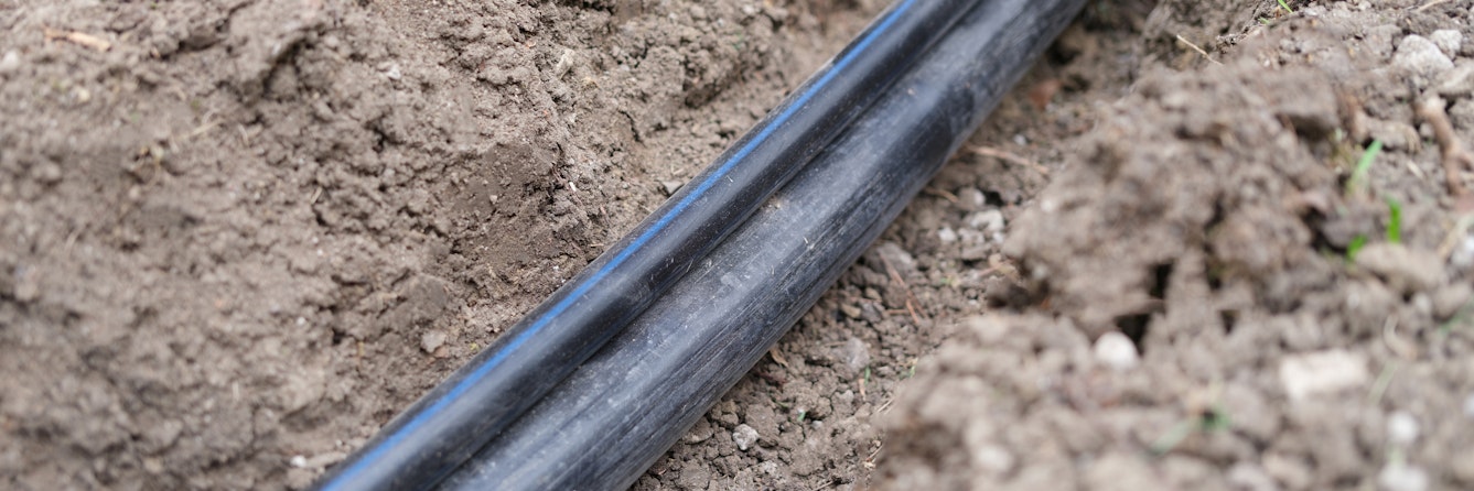
The thermal resistivity of soil, as well as additional equipment such as cable ducts, affects the capacity of underground power cables to carry currents and dissipate heat. As thermal resistivity is largely affected by moisture content, as well as other characteristics like soil porosity, the soil at some solar PV sites is replaced with a different type of soil or a mixture of cement and sand. A cement-sand mixture is likely to hold less moisture due to its proximity to the hot power cables.
In typical environmental conditions, the current-carrying capacity (CCC) of the cables is reduced as water migration occurs and a fully-loaded cable creates a dry zone in its surrounding area due to the higher temperature. The thermal resistivity of the soil decreases when the temperature rises, while the resistivity of cooler soil rises with the same water content. As a result, dry soil that has high thermal resistivity will trap heat around the cables, quickly increasing the local temperature.
How does temperature affect cables?
Cables reaching high temperatures cause water migration, resulting in the real thermal resistivity of the soil consistently becoming much higher than assumed in the project design.
Project designers can maintain favorable conditions for the transfer of heat from cable to soil by blocking the migration of water through the soil via backfilling with excavated material that has lower thermal resistivity.
When thermal resistivity in the soil is relatively high, e.g. 2.5 (K.m)/W, there should be a stabilized backfill of low thermal resistivity (1.0 (K. m)/W or less) surrounding the cables. A larger backfill area improves the thermal conditions for heat transfer, increasing cable capacity.
Cable capacity also depends on the position in which they are buried. Potential exposure to external heat sources should also be taken into account when selecting cables, as it has a direct impact on the reliability of supply.
Many countries have set recommended standards for soil thermal resistivity for the purpose of cable sizing. Standards like IEC 60287 specify the maximum current a cable can carry in certain environmental conditions and installations without the temperature exceeding the rating of the insulation material.
How to choose the right cable sizing
Thermal resistivity and its correction factor are important elements in determining correct cable sizing. Accurately measuring soil conditions for derating or modeling simulations is crucial when designing the underground circuit in a PV system, as it allows you to determine how much current the cables can carry without overheating.
Soil thermal resistivity is determined by conducting lab tests on soil samples from boreholes taken from a project location during a geotechnical survey.
At project sites where the thermal resistivity of the soil is high — which would reduce the CCC — it can be tempting to increase the size and number of underground cables in order to reach the required CCC. But this is a costly approach and only feasible where there are no constraints on the trench size or the number of cable terminations.
Rather than simply increasing the size of the conductor, it is possible to increase the CCC by making it easier for the cabling to transfer heat. This is done by releasing heat into the cable surroundings using a material with low thermal resistivity. Enclosing the cables in thermal bedding sand conducts heat away from the cabling more effectively, enabling them to operate at higher currents without exceeding their maximum allowable temperature.
The IEC 60287-1-1 and IEC 60287-2-1 standards include basic recommendations for the calculation of CCC using the following formula:

I = Current
∆ = Conductor temperature rise (K)
R = Alternating current resistance per unit length of the conductor at maximum operating temperature (Ω/m)
Wd = Dielectric loss per unit length for the insulation surrounding the conductor (W/m)
T1 = Thermal resistance per unit length between one conductor and the sheath (K m/W)
T2 = Thermal resistance per unit length of the bedding between the sheath and the armor (K m/W)
T3 = Thermal resistance per unit length of the external Sheath of the cable (K m/W)
T4 = Thermal resistance per unit length between the cable surface and the surrounding medium (K m/W)
n = Number of load-carrying conductors in the cable (conductors of equal size and carrying the same load)
λ1 = Ratio of losses in the metal sheath to total losses in all conductors in that cable
λ2 = Ratio of losses in the armoring to total losses in all conductors in that cable.
The maximum conductor temperature rating, the clearance between conduits, and the daily loss factor — which refers to how often the current is below its peak value — can all help to determine cable size.
The impact of thermal resistivity in the soil surrounding cables must be measured and taken into account when designing a solar PV project to ensure that the system operates safely. It also offers the opportunity to save on costs by coming up with creative solutions to limit heat transfer.
How RatedPower optimizes cable sizing
RatedPower solar planning platform enables project designers to calculate and set the criteria for cable sizing and layout with ease, taking into account soil resistivity and temperature. Each cable is identified by a unique code and included in the design documentation.
Learn the methodology to size the electrical equipment and the power cables of a photovoltaic plant. Download it today!
RatedPower empowers project developers to automate and optimize the analysis, design, and engineering of a PV plant at every stage of its development. Contact us today for a demonstration of how the platform can accelerate the design and engineering processes for your large-scale solar PV project!
RatedPower's energy losses and how to reduce them
Join our Product Owner, Gorka Arrieta and explore the key aspects of front-face losses, back-face losses and electrical system losses and gain tips on maximizing energy efficiency in your PV projects
Latest stories
Related posts
Technology and engineering
Innovation in renewable energy: Developments expected in 2025
We look at the 10 biggest renewable industry developments that are making a green future possible, including perovskite solar cells, green hydrogen, and more.
Updated 18 MAR, 25
Market analysis
Breaking down solar farm costs: Free template inside
Updated 27 SEP, 21
Market analysis
Solar energy in Australia: a 2021 market analysis
Updated 11 MAY, 21

- RatedPower
- Solar energy blog
- Cable sizing: Soil resistivity and temperature

